Friday, November 12, 2010

Bugs & Issues in IEEE 802.11 MAC of ns-2

The discussion can be classified as two parts. 
  1. Part 1 is about the bugs and flaws of ns-2 802.11 code. This can be fixed.
  2. Part 2 comes from ambiguous understandings of the 802.11 standard or inherent 802.11 MAC problems. These need not to be fixed.

If we increase data rate and decrease packet size simulation with wireless
network, we will get an error message: "Scheduler: Event UID not valid!",

To remove this error,
Insert the following sentence before *every* tx_resume() function call:
if(mhDefer_.busy()) mhDefer_.stop(); 
A detailed analysis can be found in http://www.dei.unipd.it/wdyn/?IDsezione=2435

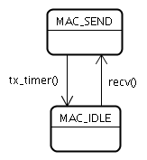
Use Defer timer for backoff in send() and tx_resume()
The backoff implementation in mac-802_11.cc does not comply with the standard. Basically, this is due to the introduction of a defer timer. The defertimer is set in send() and after a packet transmission finishes. The deferred time value is usually (DIFS+rTime) where rTime is as same as the selection of backoff timeslots from CW (Contention Window). However, the defertimer is never paused or resumed.
So, after a packet transmission, according to the IEEE 802.11 standard, the node should do backoff immediately. here in ns-code, the defertime is first set. And after timer out, in check_pktTx() function. if the channel is not idle, a backoff timer is set. Therefore, here exists a double backoff problem.
To fix this problem, the defer timer usage shall be limited to only contain DIFS or EIFS, not extended to including backoffs.
MAC Access bug: No direct access, always backoff?
According to IEEE 802.11 standard, a node should access channel directly if it sense the channel idle and still idle after at least DIFS time. Here, in thte send() of ns-2 sourcecode, we can see that, by no means, the MAC will send the DATA or RTS frame directly without backoff. It deviates from the standard and adds an additional rTime before sending DATA or RTS.

The fix of this problem is not trivial. We have to add some memory in MAC to remember an extra Idle/Busy state variable. And if channel is idle after DIFS wait, the MAC shall check this variable again to determine if this node shall go to backoff or send the packet directly.

I, personally, still prefer the design that there is always a backoff after DIFS-wait.  In this way, no nodes will take this advantage of direct access while other nodes are in backoff. It makes more sense, especially in a fair fashion.

Blocking due to Retransmission Counter not reaching limitsIn “Mac802_11::recvDATA” of ns-2.26

{.....
ssrc =0; //short retry-count set to 0
...
}
A<----->B---------------->C
From B to C, Infinite numbers of RTS get no response because SSRC cannot reach 7 (maximum allowed transmission times) because it was reset after a A-B DATA exchange
Update: This bug is fixed in new ns-2 versions.
ACK rate???
Excerpted from an ns-2 mail list discussion:
In NS-2 the ACK packet is always sent at basicRate_ (see file mac-802_11.cc). Typically this value is set to 1e6. In real world ACKis sent at the same rate as the packet that triggered it ( the preceding DATA packet).
Is this true?
no one is denying that ACKs can be sent at 11Mbps - the only debate is whether they can be sent at 11Mbps when it is not one of the rates in the basic rate set.  Because the standard requires that ACK shall be sent in one of the basic rates.
So I'd have two questions about your measurements - (1) what is the basic rate set being advertised by a real AP? (2) Is it an 11g 802.11AP or STA? (As the rules for them are slightly different.)
It's possible that ACKs are being sent out at a non-basic rate.  It's a bad thing to do as it can lead to misaligned slots (and hence more
collisions) but the difference is probably not that noticeable in the real world.

I doubt that you'll find much of a difference in simulations as the ACK
frame is pretty short, and the transmission time is dominated by the PHY
headers.

EIFS-induced Unfairness

In the follwoing scenario, two flows A->B and B->C will have dramatically different throughput.
Suppose A can hear B, but can only sense C. In other words, C is within A's carrier-sensing range but out of the communication range.

A----->B---->C
The bandwidth sharing between A and B will be around 20%-80%. This is because C's ACK frame will be sensed by A, but not decoded. So, A will wait for EIFS after this before accessing the channel again. This gives B leverage to access the channel.

Simulation example: Measuring the effects of RTS/CTS on 802.11 link

How to turn off RTS/CTS?


put this line in the TCL script.
#disable RTS for 802.11 MAC
Mac/802_11 set RTSThreshold_   3000


Simulation Topology:


Link Connectivity Graph:


Two flows are given: 1--> 3 , and 5---> 7


Simulation Parameters:
Datarate1Mbps
IFQ Length50
Routing ProtocolDSDV
Packet size1000Bytes
Packet rate25-200 per second
Transmission Range250m
Test duration150 sec.


Simulation Results:


Observations & Conclusions:
  • Observed route establish time, depends on the number of hops in DSDV is 30-50 seconds. why?
  • RTS/CTS does not improve throughout in multi-hop wireless network
  • Actully, we cannot draw general conlcusion from this specific case of flow and routing protocols.

Analysis of 802.11 MAC code in NS-2

0. MAC in ns-2


LAN is within Berkeley Architecture, WLAN cannot create with “newLan” command
Ethernet could be created as a LAN with common bandwidth and delay.

1. The general structure of MAC

related sourcecode:  mac.cc,  mac.h

MAC class is derived from Bi-Connector class.

Local Variables:
  • pktTx_ 
  • pktRx_
  • Macstate_ :
  • index_  : mac address

Basic functions of General MAC class.
  • recv (packet, handler)
    • This is the entry from upper target (a callback handler is given as a parameter) to send a packet to MAC. After the MAC transmit this packet successfully, it will use this callback handler to inform the upper target that MAC is idle and  give another packet if there are packets buffered.
  • SendUp
    • entry for receiving a packet. Sendup is function is directly called by the lower target of MAC, might be "netif" or "phy". And this function directly calls the upper_target. Because the uplink  to upper_target does not involve any phsical transmission delay, it does not need any timer and state change here. The question is that when the MAC is in MAC_RECV state? The answer is: The MAC here is supposed to be full-duplex and receive can be happened simultaneously. it does not care about collisions etc. This is a general MAC class
  • SendDown
    • used to sending packet down. Called by recv().init a timer for tx, and the timer handler is defined to call resume().
  • Handler* callback_;
    • when MAC is idle, the upper target has to be callback.
  • Resume()
    • When tx timer out, reset MAC as idle state and callback.
  • Discard
    • When a packet has to be drop, the drop_ (NsObject*) of bi-connector class has to be called to handle this, usually drop (p, why) is used. Why is a string of drop reason, in cmu-trace.h. three-character string is defined to describe those reasons in the trace file, such as "BSY", "CBK"....
mac_state

2. The 802.11 MAC

it is implemented by CMU. It is a subclass of MAC.

related sourcecode : mac-802_11.cc, mac-802_11.h, mac-timer.cc, mac-timer.h

State Machine: 


The tx_state and rx_state are two member variables. Although, actually mac cannot transmit and receive at the same time. we still hold two variables for them. The possible state is MAC_SEND, MAC_IDLE, MAC_RECV, MAC_COLL, MAC_RTS, MAC_CTS, MAC_ACK.

Local Variables:
  • pktTx_ (inherited from Mac class): 
  • pktRx_(inherited from Mac class):
  • pktCtrl_
  • pktRTS_

Basic functions:

  • recv(): the recv() function of MAC class has been overridden. Here, recv() means an incoming packet from both physical layer and upper layer.
  • send(): this function is called by recv() when it get a packet supposed to sending down.  Similarly, a callback handler is given as a parameter. Immediately, the sendDATA(p) function is called to generate an appropriate mac_header for this packet, and set this to pktTx_. Then,  follew the CSMA/CA procedures to get this packet sent.
  • sendDATA(). to compose a DATA MAC frame and set it as pktTx_
  • recvDATA(). When heard a DATA MAC frame, hand it to upper layer.

Callback to IFQ in MAC 802.11

The callback is set when a packet comes from upper layer and be handled by send(p,h). The callback is used and reset to zero in tx_resume() function of mac-802_11.cc:

void
Mac802_11::tx_resume()
{
 .....
else if(callback_) {
        Handler *h = callback_;
        callback_ = 0;
        h->handle((Event*) 0);
    }
    // change wrt Mike's code
    //SET_TX_STATE(MAC_IDLE);
   setTxState(MAC_IDLE);
}
The callback will reactivate the interface queue between mac_ and ll_ objects, see queue/queue.cc
void QueueHandler::handle(Event*)
{
        queue_.resume();
}

void Queue::resume()
{
        Packet* p = deque();
        if (p != 0) {
                target_->recv(p, &qh_);
        } else {
                if (unblock_on_resume_)
                        blocked_ = 0;
                else
                        blocked_ = 1;
        }
}
See that the queue is blocked if not "callback", thus, callback is essential to make queue work properly.Backoff
The backoff implementation in mac-802_11.cc does not comply with the standard. Basically, this is due to the introduction of a defer timer. The defertimer is set in send() and after a packet transmission finishes. The deferred time value is usually (DIFS+rTime) where rTime is as same as the selection of backoff timeslots from CW (Contention Window). However, the defertimer is never paused or resumed.
So, after a packet transmission, according to the IEEE 802.11 standard, the node should do backoff immediately. here in ns-code, the defertime is first set. And after timer out, in check_pktTx() function. if the channel is not idle, a backoff timer is set. Therefore, here exists a double backoff problem. Also, according to IEEE 802.11 standard, a node should access channel directly if it sense the channel idle and still idle after at least DIFS time. Here, ns-code also deviates from the standard and add an additional rTime before sending DATA or RTS.
 
Determine the transmission time 


txtime is calculated from the "size" variable in common header. Because all headers are present in the packet no matter what layer it is. Thus, the only way to know the packet size is to add or subtract some bytes in hdr_cmn->size(); In 802.11 MAC code, in recvDATA(), the 802.11 header size will be subtracted. And in SendDATA(), a 80211_hdr_length will be added.

Transmission Failure:
In both RetransmitRTS and RetransmitDATA functions, it is necessary to deal a packet drop :
if(ssrc_ >= macmib_.getShortRetryLimit()) {
  discard(pktRTS_, DROP_MAC_RETRY_COUNT_EXCEEDED); pktRTS_ = 0;
  /* tell the callback the send operation failed 
     before discarding the packet */
  hdr_cmn *ch = HDR_CMN(pktTx_);
  if (ch->xmit_failure_) {
                        /*
                         *  Need to remove the MAC header so that 
                         *  re-cycled packets don't keep getting
                         *  bigger.
                         */
   // change wrt Mike's code
                        //ch->size() -= ETHER_HDR_LEN11;
   ch->size() -= phymib_.getHdrLen11();
                        ch->xmit_reason_ = XMIT_REASON_RTS;
                        ch->xmit_failure_(pktTx_->copy(),
                                          ch->xmit_failure_data_);  //callback by upperlayer
                }
  //printf("(%d)....discarding RTS:%x\n",index_,pktRTS_);
  discard(pktTx_, DROP_MAC_RETRY_COUNT_EXCEEDED); pktTx_ = 0;
  ssrc_ = 0;
  rst_cw();
 } 
So, it is a way to let upper layer , such as DSR routing to know there is a route-error and need to send a route-error message.

Frame Formats in ns-2

The 802.11 header in ns-2 is not conform to the 802.11 standard. It is a different one. Thus, this overhead cannot be regarded as authentic as that of
the experiment. And the throughput measurements also seems different.

Other IEEE 802.11 features

1. Carrier Sense

This is normally done by the physical layer source code. The state of 802.11 MAC is  controlled by  some timers. Such as the  Backoff_timer. By checking if those timers are still busy, the MAC will arrange its operations correspondingly.

2. Virtual Carrier SenseRTS/CTS is an important part of code. There are functions like sendRTS ( is to form a RTS ctrl packrt) , retransmitRTS...... Basically it has to compare with RTSThreshold first, if the size is small than the threshold, there is no" virtual carrier sense" scheme used.

Understanding IEEE 802.11 MAC Standard

IEEE 802.11 MAC Dictionary

[ Back to Network Simulator 2 for Wireless Home Page ]

Undesrstanding Carrier Sense & Back Off:

Consider the following two questions about IEEE 802.11 Standard:
1. Carrier Sense is provided by the physical layer, thus, when MAC layer get a packet to transmit. It will initiate a carrier sense mechanism, and it took >= DIFS time to determine that the channel is free, thus, at least we have a delay as 128 us, right?

2. Assuming 4 nodes A,B,C,D working in  Ad-hoc mode without RTS/CTS . First, A has 10 packets (10 MPDU belongs to 1 MSDU) to transmit to B,  Thus, A access the channel, and get it. Thus, A begin a Packet-SIFS-ACK-SIFS-Packet-SIFS........ sequence. During that,  C got one packet to transmit to D, unfortunately, C sense the channel is busy, thus, C begin a backoff procedure, which he set his CWmin = 7, and Backoff time = Random() * a slottime = 3. a slot means 50 us.
Because, Each MPDU is transmitted with SIFS interval, the Backoff number cannot be decremented unless at least a DIFS is idle and the next slot is also idle. Thus C has no chance to transmit until A finished his own transmission. and After DIFS+ 3 timeslot, C will begin to transmit. Thus, we conclude that, C has no chance to challenge an existing transmission.

Then, what happened if there is a transmission failure during the 10 MPDU, it means a back-off procedure will be initiated after an EIFS, thus, at this time, A and C has the same probability to win the channel as long as the CWmin is the same.

Another interesting thing is that if node A get another MSDU (~ 5 MPDUs) to transmit to C during the period it sends the 10 MSDU. So,

" node A still has advantage to access channel, because A does not generate any back-off procedure if no transmission failure happens, and A will transmit immediately after an DIFS slot when last MSDU is finished. So, it seems that as long as a station get the access, it is always has priority to send than other stations." 

This is Wrong!!!

Citing from 802.11-1999:

"9.2.3.3:
A STA using the DCF shall be allowed to transmit if its
carrier-sense mechanism (see 9.2.1) determines that the medium is
idle at the TxDIFS slot boundary as defined in 9.2.10 after a
correctly received frame, and its backoff time has expired.
"

The last part (after "and") means: *Whenever* you have to wait DIFS,
you have to backoff, too, thus allowing other stations to content for
the medium. So, everyone has equal probability to access the channel.
The only exception is that channel is free when you access it and after waiting longer than DIFS, it is still free. Then, no backoff, send directly.
To prevent consecutive access as in above example, after a DATA packet transmission, the sending node automatically backoff after DIFS.

More specific in:
"9.2.5.2.

A backoff procedure shall be performed immediately after the end of every transmission with the More Fragments bit set to 0 of an MPDU of type Data, Management, or Control with subtype PS-Poll, even if no additional transmissions are currently queued. In the case of successful acknowledged transmissions, this backoff procedure shall begin at the end of the received ACK frame. In the case of unsuccessful transmissions requiring acknowledgment, this backoff procedure shall begin at the end of the ACK timeout interval. If the transmission is successful, the CW value reverts to aCWmin before the random backoff interval is chosen, and the STA short retry count and/or STA long retry count are updated as described in 9.2.4. This assures that transmitted frames from a STA are always separated by at least one backoff interval."

Fragmentation

As the largest MSDU is 2304 bytes limited, the MAC format for a MPDU has the data field as 0-2312, because 8 bytes used for WEP. Thus, if no fragmentation is used, the MPDU has the same length as MPDU. However, we prefer short packets to transmit to reduce the  packet corruption chance. Thus, Fragmentation is optional.More about MPDU, MSDU & PSDU and Overhaed:
MSUD is the packet from upper layer, MPDU = PSDU including everything in MAC, for example: A Packet would like:

PPDU = PSDU +PLCP header + PLCP preamble.
There are only 3 addresses in the MAC header, but the standard says 4. That's because the address is usually omitted unless a Wireless Distribution System is used and packet is for AP-AP communication.

RSSI


  • RSSI (Receive Signal Strength Indicator) Indicates how well the local station receives the remote unit's transmission in dBm. from the measurement of one packet.


  • NAV (Virtual carrier sense)

    It is interesting that the RTS set its NAV covering  to the end of whole RTS-CTS-DATA-ACK process. How about a RTS has not been ACKed with a proper CTS. Then all the nodes around the sending node will wait for such a long idle period, and just wasting the bandwidth?! The standard provides a solution, that the nodes could reset NAV if it does not hears DATA packet at some time. However, it is still seems not perfect because anyway, the NAV settings broadcasted by RTS has to be re-confirmed by a following DATA frame, the first setting in RTS seems always flexible and non-compulsive. Thus, schemes could just say, we set the NAV first to "2 x aSIFSTime) + (CTS_Time) + (2 x aSlotTime", then announce the final decision in DATA frame. This is very useful, in case that the sending node cannot be sure how long it takes to transmit without a CTS reply in some scheme
    Excerpts from 9.2.5.4
    STAs receiving a valid frame shall update their NAV with the information received in the Duration/ID field,
    but only when the new NAV value is greater than the current NAV value and only when the frame is not
    addressed to the receiving STA. Various additional conditions may set or reset the NAV, as described in
    9.3.2.2. When the NAV is reset, a PHY-CCARESET.request shall be issued.
    Figure 53 indicates the NAV for STAs that may receive the RTS frame, while other STAs may only receive
    the CTS frame, resulting in the lower NAV bar as shown (with the exception of the STA to which the RTS
    was addressed).
    A STA that used information from an RTS frame as the most recent basis to update its NAV setting is permitted
    to reset its NAV if no PHY-RXSTART.indication is detected from the PHY during a period with a duration
    of (2 x aSIFSTime) + (CTS_Time) + (2 x aSlotTime) starting at the PHY-RXEND.indication
    corresponding to the detection of the RTS frame. The ¡°CTS_Time¡± shall be calculated using the length of
    the CTS frame and the data rate at which the RTS frame used for the most recent NAV update was received.
    Figure 53¡ªRTS/CTS/data/ACK and NAV setting

    SIFS & DIFS & Slottime

    In the 1Mbps or 11M DSSS standard (1999), SIFS are 10us, and aSlottime is 20us. So, the basic reason for those values are CCA has to use 15us and a round-trip time is less than 5us, so the maximum round-trip of propagation delay is 5*300/2= 750m. However, some wireless LAN for outdoor claims coverage as several miles. In that case, it has to change this Slottime value or there are only 2 nodes in the network.
    Excerpts from standard:
    aSIFSTime and aSlotTime are fixed per PHY.
    aSIFSTime is: aRxRFDelay + aRxPLCPDelay + aMACProcessingDelay + aRxTxTurnaroundTime.
    aSlotTime is: aCCATime + aRxTxTurnaroundTime + aAirPropagationTime
    + aMACProcessingDelay.
    The PIFS and DIFS are derived by the following equations, as illustrated in Figure 58.
    PIFS = aSIFSTime + aSlotTime
    DIFS = aSIFSTime + 2xaSlotTime
    The EIFS is derived from the SIFS and the DIFS and the length of time it takes to transmit an ACK Control
    frame at 1 Mbit/s by the following equation:
    EIFS = aSIFSTime + (8xACKSize) + aPreambleLength + aPLCPHeaderLngth+ DIFS

    Beacon:

    It is not strange that in Infrastructure mode, a beacon is necessary to let AP inform the following STAs. But in ad-hoc mode , beacon is also necessary to maintain synchronization and exchange ESSID information between those ad-hoc nodes. In "ad-hoc" nodes are going to form an IBSS ( Independent Basic Service Set). It does not mean those nodes listening a same channel are automatically being in the same ad-hoc network. Actually, nodes need to join a service set identified with SSID ( Service Set IDentifier). Thus, nodes staying in the same channel still cannot communication if they belong to different "SSID". Beacons are very important in 802.11 MAC. Unfortunately, ns-2 MAC implementation of 802.11 ignores the function and overhead of "beacon".

    Broadcast:

    Broadcasting packets is also regarded as an MPDU, so it also has to obey the carrier sense & backoff. Excerpts from the standard:

    In the absence of a PCF, when broadcast or multicast MPDUs are transferred from a STA with the ToDS bit clear, only the basic access procedure shall be used. Regardless of the length of the frame, no RTS/CTS exchange shall be used. In addition, no ACK shall be transmitted by any of the recipients of the frame. Any broadcast or multicast MPDUs transferred from a STA with a ToDS bit set shall, in addition to conforming to the basic access procedure of CSMA/CA, obey the rules for RTS/CTS exchange, because the MPDU is directed to the AP. The broadcast/multicast message shall be distributed into the BSS. The STA originating the message shall receive the message as a broadcast/multicast message. Therefore, all STAs shall filter out broadcast/multicast messages that contain their address as the source address. Broadcast and multicast MSDUs shall be propagated throughout the ESS.
    There is no MAC-level recovery on broadcast or multicast frames, except for those frames sent with the ToDS bit set. As a result, the reliability of this traffic is reduced, relative to the reliability of directed traffic, due to the increased probability of lost frames from interference, collisions, or time-varying channel properties.

    Power & Energy Efficeincy

    802.11 radio consumes as much power when it is idle as when it receives transmissions. Briefly, these reasons have to do with  By contrast, with a TDMA-style MAC, it is possible to put the radio in standby mode during such intervals. That's a big difference regarding energy consumed by the radio during idle intervals.

    Weakness:

    IEEE 802.11 MAC standard is weak in solving following issues: (link layer reliability, QoS support?, power conservation)
    • Hidden Terminal .vs. Expose Terminal . This is a problem basically attributed to the difficulties to distribute "global" information about the network topology and channel state to a "local" terminal. RTS/CTS mechanism partly overcomes this problem.
    • Multi-hop .vs. Clustering. This problem is prevailing when large ad-hoc network  has difficulty  in efficient routing and a long MAC address is also increasing the overhead.
    • Link layer availability and fair utilizing. The major representative of this is the "Head of Line" problem. the first packet of the FIFO queue is re-transmitted endlessly, thereby affecting the performance ("throughout") of the network. As this also occurs in wired network, the adverse wireless environment worsen the problem.

    Further Research Issues about MAC layer of Ad-hoc Network

    1. To revamp the  well-known MACA protocol used by 802.11 from a single-cell MAC in direction that allows  neighboring cells to operate simultaneously whenever possible, thereby increasing the overall system throughput.
    2. The second challenge we discuss is the notion of a  "wireless router" or a forwarding node, whose primary function is to receive  packets from one neighbor and transmit them to a second neighbor using the  same wireless interface. This requires combining channel access functionality with that of next-hop address lookup within the network interface card without host participation.
    3. The third set of challenges arise from the effects of physical/MAC layer characteristics on  network connectivity (i.e. whether two nodes are neighbors depends on the rate used),  transport layer performance (i.e  contention for the physical channel among neighboring hops lead to packets of the same flow contending with each other) and use of  MAC contention mechanisms as a means for supporting transport-layer congestion control.

    Spectrum

    A sample spectrum "image" for IEEE 802.11 wireless LAN
     

    Monday, October 18, 2010

    MAC Interface in ns-2

    General Architecture of a mobile node in ns-2:


    the relationship of MAC could be found in ns-mobilenode.tcl. The source code:
    ........
    #
    # The following setups up link layer, mac layer, network interface
    # and physical layer structures for the mobile node.
    #
    Node/MobileNode instproc add-interface { channel pmodel lltype mactype \
      qtype qlen iftype anttype topo inerrproc outerrproc fecproc} {
     $self instvar arptable_ nifs_ netif_ mac_ ifq_ ll_ imep_ inerr_ outerr_ fec_
     
      .......    
        #
     # Link Layer
     #
     $ll arptable $arptable_
     $ll mac $mac
     $ll down-target $ifq
    
     if {$imepflag == "ON" } {
      $imep recvtarget [$self entry]
      $imep sendtarget $ll
      $ll up-target $imep
    
            } else {
      $ll up-target [$self entry]
     }
     #
     # Interface Queue
     #
     $ifq target $mac
     $ifq set limit_ $qlen
     if {$imepflag != ""} {
      set drpT [$self mobility-trace Drop "IFQ"]
     } else {
      set drpT [cmu-trace Drop "IFQ" $self]
            }
     $ifq drop-target $drpT
     if { $namfp != "" } {
      $drpT namattach $namfp
     }
             
            # Mac Layer
     #
     $mac netif $netif
     $mac up-target $ll
    
     if {$outerr == "" && $fec == ""} {
      $mac down-target $netif
     } elseif {$outerr != "" && $fec == ""} {
      $mac down-target $outerr
      $outerr target $netif
     } elseif {$outerr == "" && $fec != ""} {
      $mac down-target $fec
      $fec down-target $netif
     } else {
      $mac down-target $fec
      $fec down-target $outerr
      $err target $netif
     }
    Actually, from top to down path, the structure is  ll  --->  ifq ----> mac ---> netif . for packets going up, it is netif ---> mac --->ll. Thus, ifq is only used for down path of . however, a scheduler is also only useful to handle outgoing packets. Thus, if we want to implement a scheduler, we have to use something to replace this "ifq" and remake the interface in tcl script.

    Why List-based improvement in ns-2.27 cause problems?

    Since in ns-2.27, a "list-based improvement" is used to control the number of nodes receiving packet copies. prevX_ and nextX_ are added in MobileNode class to form a list. Before a packet is sendup, this list is sorted in ascending order. Then with the getAffectedNodes(), some nodes are picked based on (x,y) coordinates to receive the copy of the packet. This design is in WirelessChannel:sendUp() call.
    This design has a serious bug: no consideration of the case that multiple interfaces might be colocated in the same node. In this case, The node's prevX_ and nextX_ will be updated multiple times if you want to create multiple PHY interfaces to utilize multiple channels. As a result, the prevX_ of each !Mobilenode will be set to point to itself!!!!
    There are no quick fix for this. I have to rollback code to ns-2.26 to avoid segmentation fault.
    Therefore, to have multiple radio interfaces in a node, this has to be disabled.

    Ricean Fading based probabilistic Link Error

    OAR ns extensions for Fading:

    The error-part is extended from another online patch from CMU and Rice Univ.

    Cite from OAR site:
    "Although the CMU implementation results in an accurate simulation of the wireless channel for each individual flow, the fading components of channels for different flows are identical, a scenario not encountered in practice. This arises due to the fact that the index into the pre-computed channel table (used to look-up the components of fading envelope) is chosen based on the simulator's time instant, which is identical for all flows. To more realistically model the wireless channel for multiple users we modified the implementation such that channel lookup indexes are a function of the flow and time."

    How to use

    Three files:
    • prop_ricean.cc
    • prop_ricean.h
    • rice_table.txt
    A table has to be created in a file to store all fading components.
    File rice_table.txt maintains the table used by Ricean Fading Model.

    Original Description from CMU package
    III. USAGE
      There is a sample script in the simscript directory.  You will need
      this and the file "rice_table.txt".
    
      You should be able to run the sample script "rjp-sample.tcl".  This
      is just a slightly modified version of the example script
      wireless-mitf.tcl which is in the NS distribution.
    
      Parameters for the Ricean Fading:  The fading model is used to
    modulate the output of a large-scale fading model. In this case, it
    uses TwoRayGround as the large-scale model. 
      
      For the Ricean Fading model:
    
      MaxVelocity   :  This parameter determines the doppler spectrum.
          The value of this parameter is the maximum speed of any objects in the
          environment (could be nodes).  It is NOT the speed of the
          nodes themselves.
    
      RiceanK  : The Ricean K factor
    
      LoadRiceFile :  The file containing a table of in-phase and
       quadrature-phase ricean components.  This has to do with the
       computation of the fading enveloped and doesn't have to be changed. 
       Just load the provided file "rice_table.txt"  in the simscript directory.
     
    
      The provided script uses the NORT routing as the routing protocol
      (it is a NULL routing protocol).
      This is not provided with the NS distribution.  You can add nort.cc
      and nort.h to a directory called nort/ in your NS source directory,
      add nort/nort.o  to Makefile.in, run configure and then make to
      include support for this.
    
    
    I did some minor changes, and the three files can be downloaded here:

    The files prop_ricean.* should be put in the directory of ./mobile of ns source tree and the ricean_table.txt should be put in the same directory with simulation tcl-script.

    Some lines in Tcl to enable this new propagation model:

    set val(prop)           Propagation/Ricean          ;# radio-propagation model

    set prop_inst [$ns_ set propInstance_]

    $prop_inst MaxVelocity  2.5;
    $prop_inst RiceanK        6;
    $prop_inst LoadRiceFile  "rice_table.txt";

    Reference Links:

    1. Rice OAR software (http://www.ece.rice.edu/networks/software/OAR/OAR.html)
    2. CMU Additions to the NS network simulator to handle Ricean and Rayleigh fading     http://www.ece.cmu.edu/wireless/downloads.html